


.png)

.jpg)


.png)


.png)


.png)

.jpg)


.png)
.png)
.png)
.png)

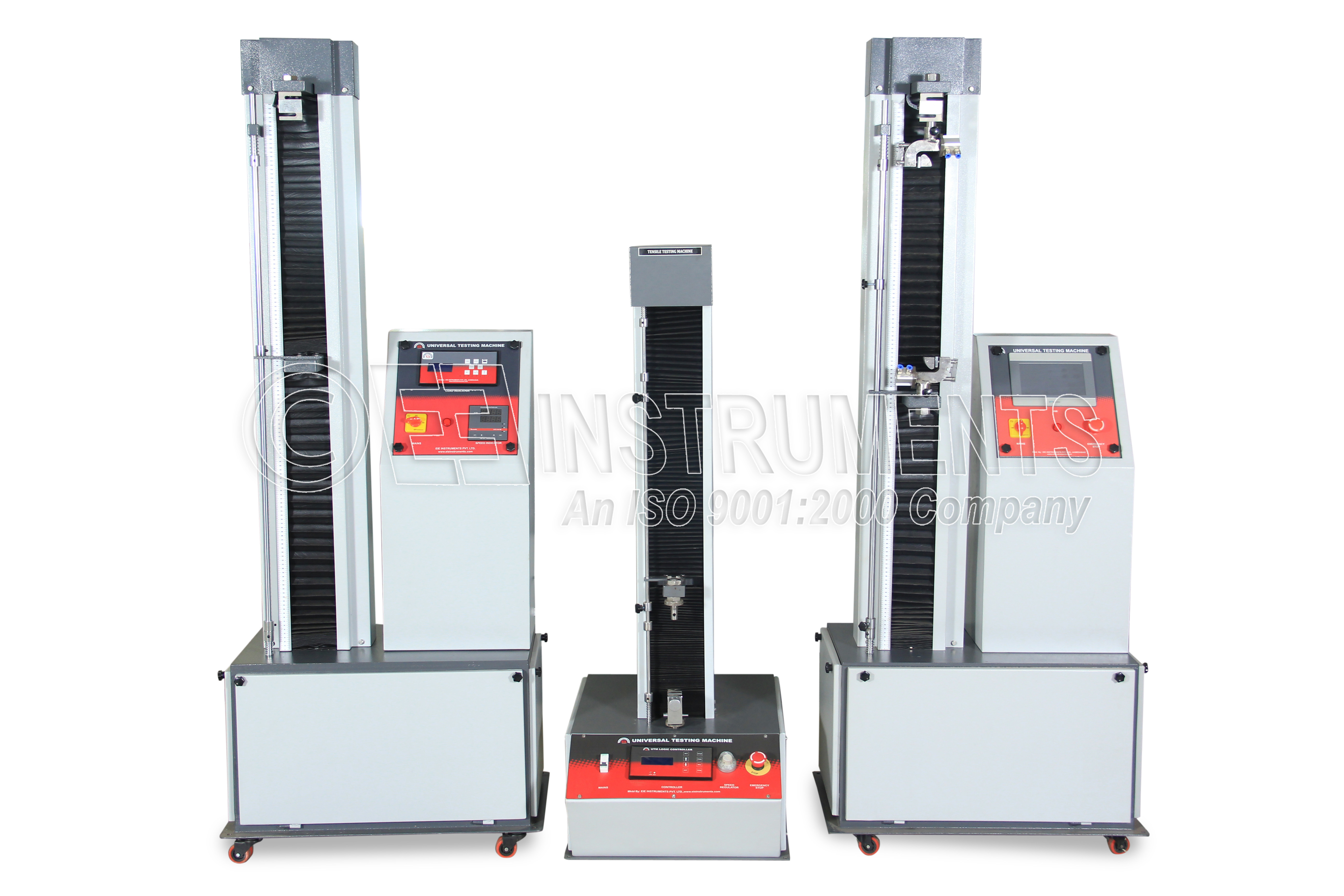
HIGH TEMPERATURE HOT MODULUS OF RUPTURE (HMOR)
Determination of the High Temperature Hot modulus of Rupture (HMOR) / Ceramic Complying with IS:1528(Part 20)-1993 & ISO:5013-1985 for a batch of 5 Samples - Sending - regarding.
-
More Information
-
Technical specification
-
Accessories
-
Spares
More Information
Technical specification
|
FURNACE STRUCTURE |
|
|
Furnace |
Chamber furnace with preheating zone |
|
Shell size and useful volume |
≈700 x 700 x 1500 mm and 200 x 200 x 400 mm |
|
Shell Construction |
Double Wall High quality fabrication of M. S Body and M. S. Angle’s structure with proper stiffeners and neat powder coat painting |
|
Door Construction |
Sophisticated system to avoid heat loss made by Stainless steel door with proper insulation |
|
Furnace stand & panel box |
Control panel box with a door coupled with furnace stand to a height of 1 meter |
|
Insulation |
High alumina Bricks C-29 Grade Cumi make & back up by mechanically pressed zirconia blend ceramic fiber. |
|
Skin Temperature |
Double wall structure & special air circulating fan will be provided to maintain the skin temperatures just above ambient |
|
Loading rod & bottom bearing edges |
Silicon carbide |
|
HEATING SYSTEM |
|
|
Heating elements |
Silicon carbide (twelve numbers with even distribution) |
|
Make |
I SQUIRED R, USA (Imported) |
|
Type of element |
Solid type |
|
Hot zone length |
190mm |
|
Total length of element |
600mm |
|
Resistance of the element |
≈1 ohms |
|
Furnace operation |
Three phase / AC |
|
Power |
10 kW |
|
Maximum Temperature |
1500°C |
|
Working Temperature |
1400°C |
|
Electrical line requirement |
32A – MCB (three phase with neutral) has to be arrange by the customer |
|
CONTROL SYSTEM. |
|
|
Temperature Control |
TAIE (8x2=16 segment) PID programmer cum Digital Temperature controller cum Indicator (Imported) |
|
Temperature sensor |
Pt+Rh13%/Pt – ‘R’ type thermocouple along with Recrystalised alumina beads and sheath |
|
Accuracy |
±1°C |
|
Power Control |
through the phase angle controlled thyristor |
|
Indications |
a) Ammeters |
|
b) Mains Indicator |
|
|
c) Out put Indicator |
|
|
Control switches |
Mains on, out put on |
|
Safety |
Input, out put fuses |
|
SPECIMAN & TESTING |
|
|
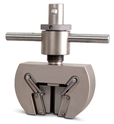
Test specimen size & Numbers |
25 X 25 X 150mm & 5Numbers |
|
Bending mode |
3 point |
|
Distance between the support |
125mm |
|
Maximum load |
200kg |
|
Loading device |
Motorized load (Automatic) |
|
Measuring Accuracy |
±1% |
|
Loading speed |
0.5 ~ 4.0kg/sec |
|
Digital out puts |
1. breaking load (Rupture load) |
|
AUTOMATION SYSTEM |
|
|
Control System |
1.Programmable logical controller(PLC) |
|
2. Human Machine Interface(HMI) |
|
|
PROGRAMMABLE LOGICAL CONTROLLER (PLC) |
|
|
Input Points |
8 Inputs |
|
Insulation Method |
Photo-coupler insulation |
|
Rated Input Voltage /Current |
DC24V / 4mA |
|
Operation Indication Input On |
LED On |
|
COMMON Method |
8 points |
|
Output Points |
8 Output |
|
Insulation Method |
Relay insulation |
|
Rated Input Voltage /Current |
DC 24V, 2A (Resistive load) / AC220V, 2A |
|
Operation Indication Output On |
LED On |
|
Minimum Load Voltage/Current |
DC 5V / 1mA |
|
Maximum Load Voltage/Current |
AC250V or DC125V / 2A |
|
HUMAN MACHINE INTERFACE (HMI) |
|
|
Screen Size |
5” Wide |
|
Resolution |
800 X 480 |
|
LCD |
TFT 65,536 |
|
Brightness |
350 cd / m2 |
|
Touch Type |
Analog |
|
CPU |
32 bit RISC |
|
Operating Power |
24Vdc (DC 20 – 28 V)15 watts |
|
Internal Communication |
RS-232C |
|
External Communication |
RS-232C |
|
RS-422/485 |
|
|
External Dimension (W x H x D) |
206 x 136 x 64 (mm) |
|
Front Enclosure |
IP65F |