Construction Details :
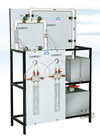
- The setup consists of sump tank, pump, orifice meter, venturimeter & measuring tank.
- The entire system is mounted on a sturdy MS frame.
- The apparatus consists of two pipelines emerging out from a common manifold.
- One pipeline contain a Venturimeter and other contain an Orifice meter.
- The pressure tapings from the Venturimeter and Orifice meter are taken to differential manometer to measure pressure difference.
- The Venturimeter & Orifice meter are connected in parallel and anyone of them can be put in operation by operating valves provided at the downstream.
- These valves can also regulate the flow.
- Present set‑up is self‑contained water re‑circulating unit.
- Flow control valve and by‑pass valve are fitted in water line to conduct the experiment on different flow rates.
- Flow rate of water is measured with the help of measuring tank and stopwatch.
|
Sump tank capacity |
With flow - 600 mm x 400 mm x 300 mm |
|
Measuring tank size |
300 mm x 400 mm x 400 mm |
|
Mercury Manometers |
Differential type, 150 0 150 mm |
|
Line |
Each line provided with flow control valve for setting of different flow rates. |
|
Pressure tubes |
Of different pipe lines are connected to common manometer through cocks. Easy to operate and replacement of Venturimeter & Orifice meter. |
|
Flow control valve |
At the end of each line assures full running of pipe. |
|
Stop Watch |
Digital Stop Watch with 1/100 second Accuracy can be supplied at extra cost. |
|
Manual |
Detailed Technical Manual supplied. However, On site Training at extra cost. |




.png)
.jpg)



.png)






.png)

.png)

.jpg)


.png)
.png)

.png)
.png)
