


.png)
.jpg)


.png)


.png)

.png)

.jpg)


.png)
.png)

.png)
.png)


The objective of this apparatus is :
- To visualize the phenomena of Hydraulic Jump in a sluice gate.
- To compare the upstream and downstream depth of flows from experimental data to theoretical data.
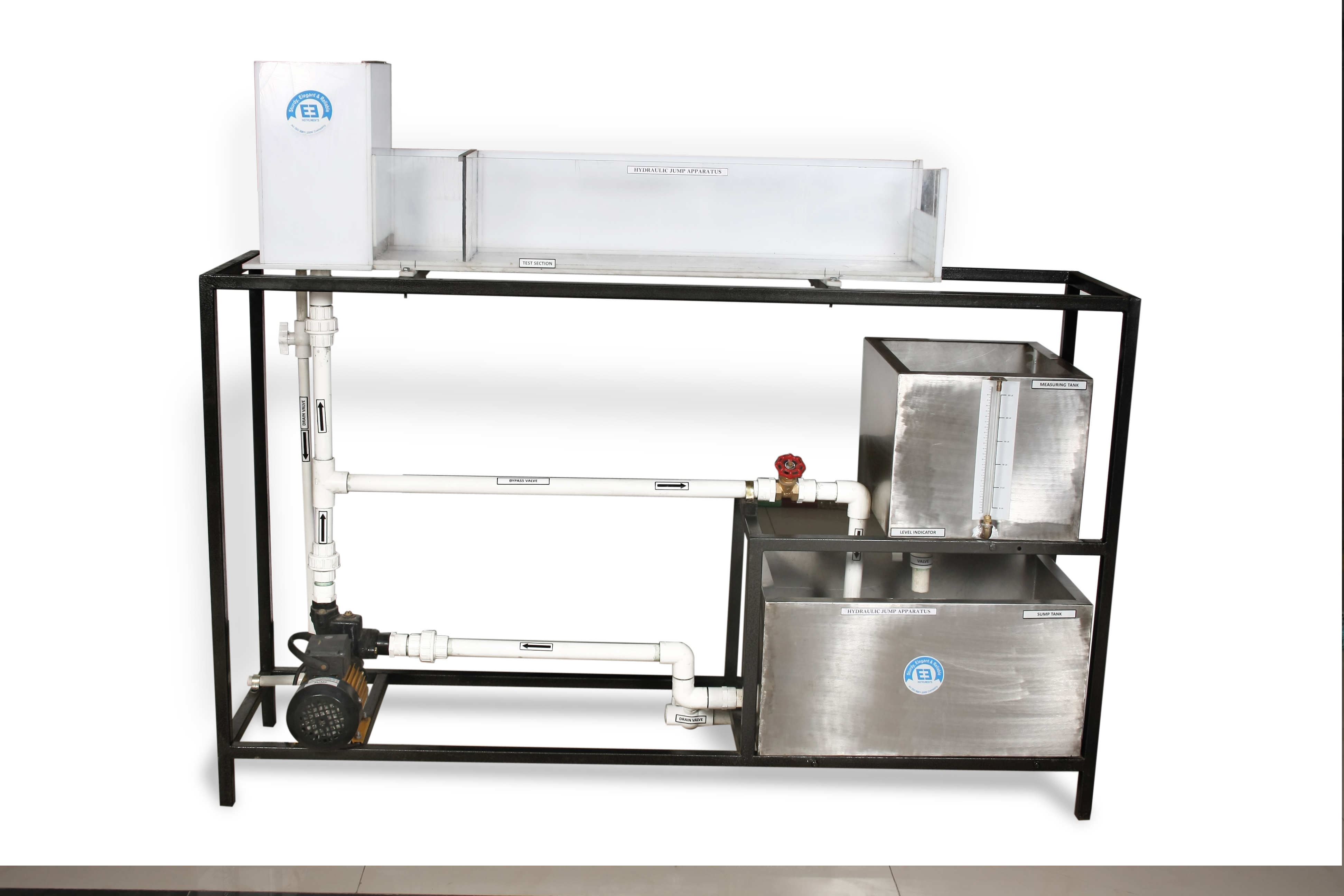
Construction Details :
The setup consists of sump tank, pump, constant head tank & measuring tank. The entire system is mounted on a sturdy steel frame. The exterior body of the unit is powder coated in attractive shades. Flow control valve and by pass valve are fitted in flow line to conduct experiment on different flow rates. Flow rate is measured with the help of stop watch and measuring tank. The flow is established via a constant head tank. This is a simple source condition that enforces a constant elevation head of water in a reservoir be available to drive a flow. The facility we are using creates a constant head tank by filling the head with water from a pump at a rate greater than the water flows out under the sluice gate.
|
Channel Size |
(1000 x 250 x 200) mm |
|
Test Section |
Transparent tank with sluice gate |
|
MOC of Test Section |
Acrylic |
|
Volumetric tank capacity |
48 liters |
|
MOC of Constant head tank |
SS 304 powder coated |
|
Sump tank capacity |
75 liters |
|
MOC of Sump tank |
SS 304 powder coated |
|
Stop Watch |
Digital stop watch |
|
Water Circulating Pump |
Motor 0.5 HP, Mono block type, 0 60 Liter/min |
|
Piping |
with necessary valves and fittings |
|
Stop Watch |
Digital Stop Watch with 1/100 second Accuracy can be supplied at extra cost |
|
Manual |
Detailed Technical Manual supplied. |